Understanding the Basics of I2C Interface Controllers
I2C interface controllers play a crucial role in enabling communication between electronic devices. They act as a bridge, allowing microcontrollers to exchange data with peripherals like sensors, displays, and memory chips. This communication simplifies multi-device setups by reducing the number of connections needed.
The demand for I2C has grown significantly due to its efficiency in connecting multiple devices. For example:
The global Interface Bridge ICs market was valued at $1.2 billion in 2023.
It is projected to reach $2.5 billion by 2032, growing at a CAGR of 8.1%.
In modern electronics, I2C is essential for IoT devices, consumer gadgets, and industrial applications. Its simplicity and reliability make it a preferred choice for low-speed, short-range communication.
Why Choose I2C for Communication?
Advantages of I2C Interface Controllers
I2C interface controllers offer several benefits that make them ideal for multi-device communication. You only need two wires, SDA (data line) and SCL (clock line), to connect multiple devices. This simplicity reduces the complexity of wiring and saves space on circuit boards. Each device on the I2C bus has a unique address, allowing you to connect and control multiple devices without interference.
Here are some key advantages of I2C:
Efficient Multi-Device Communication: I2C connects multiple sensors, displays, and memory devices to a single microcontroller. For example:
In sensor networks, I2C enables real-time data collection from multiple sensors in IoT applications.
It controls LCD and OLED display modules in consumer electronics.
It facilitates data transfer between EEPROM or flash memory chips and processing units.
Simplified Protocol: The protocol is easy to implement and requires minimal commands to control thousands of devices.
Acknowledgment Mechanism: I2C ensures reliable communication by confirming data transfer between devices.
The I2C communication bus requires only two bidirectional lines – a serial data line (SDA) and a serial clock line (SCL). Every device connected to the bus has its own unique address and can act as either a receiver or transmitter.
Comparing I2C with UART and SPI Protocols
When choosing a communication protocol, you need to consider factors like speed, complexity, and device compatibility. I2C, UART, and SPI are the most common protocols, but each has unique features.
| Feature | I2C Interface Controllers | UART | SPI |
|---|---|---|---|
| Number of Bus Lines | 2 (SDA, SCL) | 2 (TX, RX) | 4 or more |
| Device Connectivity | Multiple devices on same bus | Point-to-point | Multiple devices (with chip select) |
| Speed | 100 kbps to a few Mbps | Up to 1 Mbps | Over 100 Mbps |
| Real-time Performance | Less predictable (clock stretching) | Predictable | Highly predictable |
I2C stands out for its simplicity and ability to connect multiple devices on the same bus. Unlike UART, which supports only two devices, or SPI, which requires more wires, I2C offers a balance between efficiency and scalability. However, if you need higher speeds or real-time performance, SPI might be a better choice.
Real-World Applications of I2C
I2C plays a vital role in modern electronics. Its versatility and simplicity make it suitable for a wide range of applications. You’ll find I2C in:
Consumer Electronics: It controls displays, touchscreens, and audio components in devices like smartphones and tablets.
IoT Devices: I2C connects sensors and actuators in smart home systems, wearables, and industrial IoT setups.
Automotive Systems: It enables communication between sensors, control units, and displays in vehicles.
Medical Devices: I2C facilitates data transfer in diagnostic equipment and patient monitoring systems.
These examples highlight how I2C simplifies communication in complex systems, making it a preferred choice for engineers and developers.
Hardware Basics of I2C
Understanding SDA and SCL Signals
The I2C bus relies on two critical signals: SDA (Serial Data Line) and SCL (Serial Clock Line). These lines enable communication between devices on the bus. SDA carries the data, while SCL synchronizes the data transfer by providing a clock signal. Both lines are open-drain, meaning they can only pull the signal low. To maintain a default high state, external pull-up resistors are required.
Proper wiring is essential for reliable communication. Use appropriate gauge wires to minimize resistance, especially for longer distances. A clean layout reduces interference and crosstalk between the SDA and SCL lines. Assign unique addresses to each slave device to avoid conflicts on the bus. Additionally, ensure the bus speed is compatible with all connected devices to prevent data errors.
Tip: In noisy environments, consider using shielding or twisted pair cabling to maintain signal integrity.
Here’s a table summarizing some common microcontroller implementations of I2C systems:
| Implementation | Description |
|---|---|
| PIC18F442 Microcontroller | Includes an I2C peripheral supporting Standard- and Fast-mode I2C, with an application circuit for data collection from a 16-bit ADC. |
| MAXQ2000 Microcontroller | Capable of bit-banging Standard-mode, Fast-mode, and Hs-mode I2C signals, with a general-purpose schematic provided. |
| DI2CM IP Core | Converts a parallel interface to an I2C interface, supporting Hs-mode I2C with clock speeds up to 3.4MHz. |
The Role of Pull-Up Resistors in I2C
Pull-up resistors play a crucial role in the operation of the I2C bus. They ensure that the SDA and SCL lines remain in a high state when no device is actively pulling them low. Without these resistors, the lines would float, leading to unpredictable behavior.
The value of the pull-up resistor affects both the rise time of the signals and the current flow. Lower resistor values result in faster rise times but increase power consumption. Higher values reduce current flow but may cause slower rise times, potentially leading to errors. For most applications, a resistor value between 1 kΩ and 4.7 kΩ provides a good balance.
Here’s a table showing the impact of different resistor values:
| Resistor Value | Effect on Current Flow | Effect on Rise Time | Potential Issues |
|---|---|---|---|
| 1 kΩ - 4.7 kΩ | Higher current flow | Faster rise times | Increased power consumption |
| 10 kΩ | Lower current flow | Slower rise times | Potential bus errors |
When designing your I2C system, calculate the total bus capacitance (CBUS) based on all connections and traces. This value influences the choice of pull-up resistors. Ensure the resistors allow the bus to be pulled low adequately, considering the maximum sink current of the devices.
Master-Slave Architecture in I2C Communication
The I2C protocol uses a master-slave architecture. The master device initiates communication and controls the clock signal on the SCL line. Slave devices respond to the master’s requests based on their unique addresses. This structure allows multiple devices to share the same bus without interference.
Each slave device must have a unique address to avoid conflicts. The master sends the address of the target slave during communication. If the address matches, the slave acknowledges and participates in the data transfer. This system ensures efficient communication between multiple devices on the same bus.
Here’s a table summarizing performance results for I2C slave architectures:
| Device Family | Utilization (LUTs) | Language | fMAX (MHz) | I/O Pins |
|---|---|---|---|---|
| iCE40™ | 456 | Verilog | 97 | 68 |
To optimize performance, choose devices that support the required bus speed and address range. For example, the MachXO2™ family supports I2C slave peripherals with embedded function blocks, offering high reliability and flexibility.
Note: You can find detailed documentation and source code for I2C slave peripherals on the Lattice Semiconductor website.
Protocol Basics of I2C
Start and Stop Conditions in I2C
The start and stop conditions are essential for the i2c communication protocol. These conditions signal the beginning and end of communication on the i2c bus. The start condition occurs when the SDA line transitions from high to low while the SCL line remains high. This tells all i2c devices on the bus that a communication session is starting. The stop condition happens when the SDA line transitions from low to high while the SCL line stays high, signaling the end of communication.
Timing plays a critical role in these conditions. For example:
| Condition | Timing Specification |
|---|---|
| Start Condition | Hold Time (tHD;STA): Minimum time data must be low before SCL goes low. |
| Measured from 30% amplitude of SDA LOW to 70% of SCL LOW. | |
| Stop Condition | Setup Time (tSU;STO): Minimum time between 70% of SCL rising and 30% of SDA rising. |
| No hold time requirement for stop condition. |
These precise timings ensure reliable communication and prevent errors on the i2c bus.
Data Frames and Acknowledgment Mechanisms
In i2c communication, data is transmitted in frames. Each frame consists of 8 bits, followed by an acknowledgment (ACK) or no-acknowledgment (NACK) bit. The acknowledgment mechanism ensures that the receiving device has successfully received the data. If the receiver sends an ACK, the communication continues. If it sends a NACK, the master device may retry or terminate the session.
An i2c message typically includes the following components:
A start condition.
One or more data frames.
A stop condition or a repeated start condition.
The structure of an i2c message includes:
Address Frame: Contains the 7-bit or 10-bit address of the target slave device and a read/write bit.
Data Frames: Each frame is 8 bits, followed by an ACK or NACK.
Control Bits: Start condition, stop condition, and optional repeated start.
This structure ensures efficient and reliable communication between i2c devices.
Communication Flow Between Master and Slave Devices
The i2c communication bus uses a master-slave architecture. The master device initiates communication and controls the clock signal on the SCL line. Slave devices respond based on their unique addresses. This setup allows multiple devices to share the same i2c bus without interference.
Here’s how the communication flow works:
The master sends a start condition to signal the beginning of communication.
It transmits the address of the target slave device along with a read/write bit.
The slave acknowledges by sending an ACK if the address matches.
Data transfer begins, with the master controlling the clock and the slave sending or receiving data.
The master sends a stop condition to end the communication.
Timing parameters ensure smooth operation. For example:
| Symbol | Parameter | Units |
|---|---|---|
| fSCL | SCL clock frequency | kHz |
| tHD(STA) | Hold time (repeated) start condition | µs |
| tLOW | Low period of the SCL pin | µs |
| tHIGH | High period of the SCL pin | µs |
| tSU(STA) | Set-up time for a repeated start condition | µs |
| tHD(DAT) | Data hold time | µs |
| tSU(DAT) | Data set-up time | ns |
| tr | Rise time for SDA signals | ns |
| tf | Fall time for SDA signals | ns |
| tSU(STO) | Set-up time for stop condition | µs |
By following these steps and timing requirements, you can ensure reliable communication between master and slave devices on the i2c bus.
Advanced Features of I2C
Exploring 10-Bit Addressing
The standard 7-bit addressing mode in I2C works well for most applications. However, as systems grow more complex, you may need to connect more than 127 devices on the same I2C bus. This is where 10-bit addressing becomes essential. It expands the address space, allowing you to connect thousands of devices without conflicts. This feature is particularly useful in industrial and automotive systems where multiple sensors and controllers operate simultaneously.
Here’s a comparison between 7-bit and 10-bit addressing:
| Feature | 7-bit Addressing | 10-bit Addressing |
|---|---|---|
| Address Space | Limited to 127 devices | Supports more than 127 devices |
| Overlapping Addresses | High chance of conflicts | Reduces conflicts with unique addresses |
| Dual Addressing Capability | Not available | Enabled through external configuration |
| Address Frame Size | 1 byte | 2 bytes |
If your project involves a large number of I2C devices, consider using 10-bit addressing to avoid address conflicts and improve scalability.
Repeated Start Conditions in I2C
Repeated start conditions are a powerful feature of the I2C protocol. They allow you to initiate a new communication session without releasing the bus. This is especially useful when you need to send multiple commands or read data from a device without interruption. For example, you can send a write command to configure a sensor and immediately follow it with a read command to retrieve data, all within the same session.
To create a repeated start condition, the master device sends another start signal instead of a stop signal after the first data frame. This keeps the bus active and prevents other devices from interfering. Repeated starts are crucial for applications requiring precise timing or uninterrupted data flow, such as real-time monitoring systems.
The Concept of Clock Stretching
Clock stretching is a mechanism that ensures smooth communication between devices with different processing speeds. When a slave device needs more time to process data, it can hold the clock line (SCL) low, effectively pausing the communication. The master device must wait until the slave releases the clock line before continuing.
This feature is particularly useful when working with slower devices or when handling large data transfers. For instance, if a sensor requires additional time to prepare data, it can use clock stretching to signal the master to wait. However, not all I2C devices support this feature, so you should verify compatibility when designing your system.
Tip: If you experience communication delays, check if clock stretching is enabled and supported by your devices.
I2C interface controllers simplify communication between devices, making them indispensable in embedded systems. Their two-wire design reduces complexity and cost, while features like multi-master support and collision detection ensure reliable operation. You can connect multiple devices, even at varying speeds, using this versatile protocol.
Developed in the 1980s, I2C remains a preferred choice for low-bandwidth, short-distance communication. Its ability to handle multiple data speeds and support 10-bit addressing makes it ideal for modern applications. For further exploration, resources like the Embedded Systems Academy and NXP user manuals provide detailed insights into I2C functionality.
Tip: Dive deeper into I2C validation tools to optimize your designs and ensure interoperability across devices.
FAQ
What does I2C stand for, and why is it important?
I2C stands for Inter-Integrated Circuit. It simplifies communication between multiple devices using just two wires. You can connect sensors, displays, and memory chips efficiently, making it essential for embedded systems and modern electronics.
How many devices can you connect to an I2C bus?
You can connect up to 127 devices using 7-bit addressing. If you use 10-bit addressing, the number increases significantly, allowing thousands of devices to communicate on the same bus.
Can I2C handle long-distance communication?
I2C works best for short distances, typically under a few meters. For longer distances, you might need signal boosters or alternative protocols like RS-485.
What happens if two devices share the same address?
Address conflicts can disrupt communication. To avoid this, assign unique addresses to each device. Some devices allow you to configure their address using jumpers or software.
Is I2C faster than SPI?
No, SPI is faster than I2C. However, I2C is more efficient for connecting multiple devices due to its two-wire design and addressing system. Choose based on your project's speed and complexity needs.
Tip: Use I2C for simplicity and scalability, and SPI for high-speed requirements.
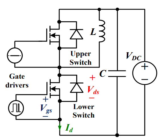 Discovering New and Advanced Methodology for Determining the Dynamic Characterization of Wide Bandgap DevicesSaumitra Jagdale15 March 20242345
For a long era, silicon has stood out as the primary material for fabricating electronic devices due to its affordability, moderate efficiency, and performance capabilities. Despite its widespread use, silicon faces several limitations that render it unsuitable for applications involving high power and elevated temperatures. As technological advancements continue and the industry demands enhanced efficiency from devices, these limitations become increasingly vivid. In the quest for electronic devices that are more potent, efficient, and compact, wide bandgap materials are emerging as a dominant player. Their superiority over silicon in crucial aspects such as efficiency, higher junction temperatures, power density, thinner drift regions, and faster switching speeds positions them as the preferred materials for the future of power electronics.
Read More A Comprehensive Guide to FPGA Development BoardsUTMEL11 September 20257937
This comprehensive guide will take you on a journey through the fascinating world of FPGA development boards. We’ll explore what they are, how they differ from microcontrollers, and most importantly, how to choose the perfect board for your needs. Whether you’re a seasoned engineer or a curious hobbyist, prepare to unlock new possibilities in hardware design and accelerate your projects. We’ll cover everything from budget-friendly options to specialized boards for image processing, delve into popular learning paths, and even provide insights into essential software like Vivado. By the end of this article, you’ll have a clear roadmap to navigate the FPGA landscape and make informed decisions for your next groundbreaking endeavor.
Read More Applications of FPGAs in Artificial Intelligence: A Comprehensive GuideUTMEL29 August 20252195
This comprehensive guide explores FPGAs as powerful AI accelerators that offer distinct advantages over traditional GPUs and CPUs. FPGAs provide reconfigurable hardware that can be customized for specific AI workloads, delivering superior energy efficiency, ultra-low latency, and deterministic performance—particularly valuable for edge AI applications. While GPUs excel at parallel processing for training, FPGAs shine in inference tasks through their adaptability and power optimization. The document covers practical implementation challenges, including development complexity and resource constraints, while highlighting solutions like High-Level Synthesis tools and vendor-specific AI development suites from Intel and AMD/Xilinx. Real-world applications span telecommunications, healthcare, autonomous vehicles, and financial services, demonstrating FPGAs' versatility in mission-critical systems requiring real-time processing and minimal power consumption.
Read More 800G Optical Transceivers: The Guide for AI Data CentersUTMEL24 December 20251024
The complete guide to 800G Optical Transceiver standards (QSFP-DD vs. OSFP). Overcome supply shortages and scale your AI data center with Utmel Electronic.
Read More Xilinx FPGAs: From Getting Started to Advanced Application DevelopmentUTMEL09 September 20252876
This guide is your comprehensive roadmap to understanding and mastering the world of Xilinx FPGA technology. From selecting your first board to deploying advanced AI applications, we'll cover everything you need to know to unlock the potential of these remarkable devices. The global FPGA market is on a significant growth trajectory, expected to expand from USD 8.37 billion in 2025 to USD 17.53 billion by 2035. This surge is fueled by the relentless demand for high-performance, adaptable computing in everything from 5G networks and data centers to autonomous vehicles and the Internet of Things (IoT). This guide will walk you through the key concepts, tools, and products in the Xilinx ecosystem, ensuring you're well-equipped to be a part of this technological revolution.
Read More
Subscribe to Utmel !
![AT88SC25616C-PU]() AT88SC25616C-PU
AT88SC25616C-PUMicrochip Technology
![FM3164-G]() FM3164-G
FM3164-GCypress Semiconductor Corp
![HCS301-I/P]() HCS301-I/P
HCS301-I/PMicrochip Technology
![L9660TR]() L9660TR
L9660TRSTMicroelectronics
![MOC3062VM]() MOC3062VM
MOC3062VMON Semiconductor
![MOC3020SR2M]() MOC3020SR2M
MOC3020SR2MON Semiconductor
![FGBS3040E1-F085]() FGBS3040E1-F085
FGBS3040E1-F085ON Semiconductor
![ATSHA204-TSU-T]() ATSHA204-TSU-T
ATSHA204-TSU-TMicrochip Technology
![AD8196ACPZ]() AD8196ACPZ
AD8196ACPZAnalog Devices Inc.
![TLE8110EDXUMA1]() TLE8110EDXUMA1
TLE8110EDXUMA1Infineon Technologies


